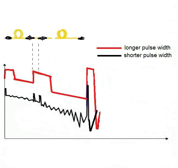
 All OTDRs regardless of brand have four basic setup requirement i.e. the OTDR user is required to key in these four basic data parameters into OTDR in order to get good and accurate fiber trace analysis. The required data parameters are :- What is Pulse Width? 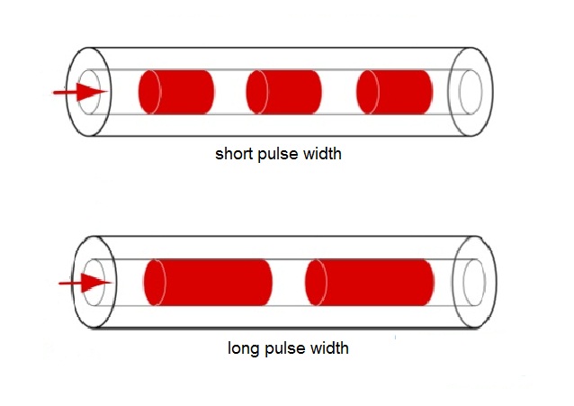
3 Comments
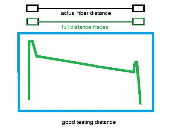
 All OTDRs regardless of brand have four basic setup requirement i.e. the OTDR user is required to key in these four basic data parameters into OTDR in order to get good and accurate fiber trace analysis. The required data parameters are :- Fiber Optics Testing Range or Distance of Fiber Optics to Test Many OTDRs have automatic length detection functions unless the end-user knows the approximate fiber distance then testing range can be set manually. The following diagrams provide OTDR traces in accordance to OTDR testing range settings. Too Short Testing Range 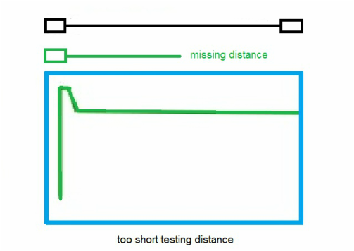
Too Long Distance Range 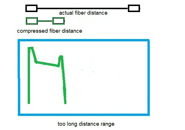
Good Distance Range
|
AuthorI have been in the field of fiber optics since early 1990s. I gained fiber optics skills and knowledge via my working experience as end-user, main contractor and sub-contractor and finally as an optical fiber enterpreneur. Archives
January 2017
Categories
All
|


 RSS Feed