SINARAN OPTIK
  • HOME
  • Our Services
    • Hands-ON Training >
      • 1-Hari OTDR Fiber Optik Praktikal (Melayu)
      • Ujian Kecekapan Fiber Optik
      • 1-Hari Pengujian & Pentauliahan
      • 2-Hari Fiber Optik Praktikal (Melayu)
      • 4-Hari Fiber Optik Praktikal (Melayu)
    • Sijil Kecekapan >
      • MASUK UJIAN CA
    • Accessories >
      • Patchcords
      • Pigtails
      • ProtectionSleeves
    • Test Gears & Tool Kits
    • Fiber Optics Case Studies
  • Contact Us
  • Why Us
    • Trainer's Profile
    • Our Esteemed Clients
    • Hands-ON Training Photos
    • Why Attend Our Fiber Optics Training?
  • My Blogs
    • Fiber Optics Blog
    • Biz Blog (In Malay)

Submarine Fiber Optics Cable Installation

6/24/2015

0 Comments

 
  1. This project was undertaken in mid 1990s for EPMI (Esso Production Malaysia Incorporated - later sold to PETRON) offshore east cost of Malaysia Peninsular
  2. The fiber optics cable was to link main oil platform to another satellite oil platform to ensure smooth communication data & voice transfer.
  3. The submarine cable was of hybrid type i.e. power, fiber optics and copper incorporated into one cable.
  4. The power cable, fiber optics cable and copper cable were separated and terminated individually at the platform lower base.
  5. Another type of fiber optics cable was  installed from the termination point up to platform communication room.
0 Comments

Iron Ring & The Ritual of The Calling of an Engineer

6/16/2015

0 Comments

 
The Iron Ring is a ring worn by many Canadian-trained engineers, as a symbol and reminder of the obligations and ethics associated with their profession. From a concept originated in 1922, the ring is presented to graduates in a closed ceremony known as The Ritual of the Calling of an Engineer, developed with the assistance of English poet Rudyard Kipling.
Picture
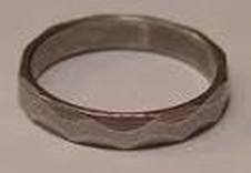
The ring symbolizes the pride which engineers have in their profession, while simultaneously reminding them of their humility. The ring serves as a reminder to the engineer and others of the engineer’s obligation to live by a high standard of professional conduct. It is not a symbol of qualification as an engineer – this is determined by the provincial and territorial licensing bodies.
Picture
Picture
0 Comments

OTDR Setup -  Index of Refraction & Fiber Distance 

6/2/2015

5 Comments

 
Picture
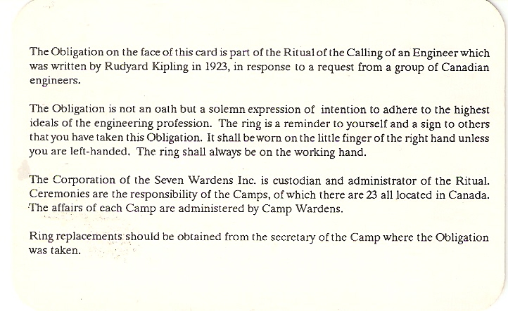
All OTDRs regardless of brand have four basic setup requirement i.e. the OTDR user is required to key in these four basic data parameters into OTDR in order to get good and accurate fiber trace analysis.

The required data parameters are :-
  1. Testing Range - Refer to Article HERE
  2. Pulse Width - Refer to Article HERE
  3. Index of Refraction 
  4. Averaging Time
Index of Refraction
Picture
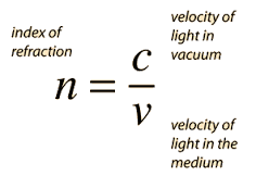
The relationship between distance and velocity or speed is as shown below -
You can review previous article on Index of Refraction HERE or HERE

As previously mentioned index of refraction measures the speed of light in optical medium. It is a function of velocity of light in vacuum and velocity of light in the opticel fiber medium or simply stated as below -

Picture
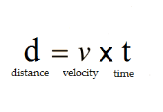
Velocity of light in fiber optics can be further expressed in terms of velocity of light in vacuum and index of refraction. This is done by rearranging the index of refraction equation as stated above.
Picture
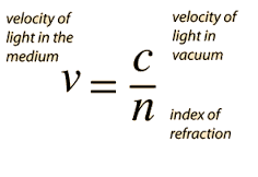
Knowing that C or velocity of light in vacuum is a constant value
Picture
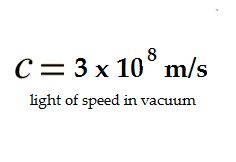
Then the distance of fiber optics as measured by OTDR can be simplied as shown below
Picture
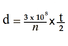
The index of refraction, n,  is a known value which can be obtained from the fiber optics manufacturer. While t , OTDR pulse width  and its backscatter light travelling time , can be measured by OTDR automatically ie. the initial time laser pulse width launched into fiber optics and time taken by backscattered light returned back into OTDR.

Therefore, the measured of fiber optics distance is a function of index of refraction.
As value of IOR increases the measured fiber optic distance or length is getting shorter.
Picture
As value of IOR decreases the measured fiber optic distance or length is getting longer.
Picture
If the OTDR index of refraction does not match to that of fiber optics under testing IOR then the OTDR distance traces might show the incorrect results. 

If the fiber optics under testing IOR is not known, then the end-user can use the OTDR default  IOR setting.

Typical fiber optics IOR value is between 1.4000 to 1.6000

Picture
Rule of Thumb
Always obtain the fiber optics Index of Refraction values from corresponding fiber optics manufacturer.
5 Comments

Fiber Optics Mechanical Splicing

6/1/2015

1 Comment

 
What is fiber optics splicing ?
Fiber Optics splicing is the process of jointing or holding two fibers together

There are two methods of fiber optics splicing namely :-
a. Fiber Optics Mechanical Splicing
Picture
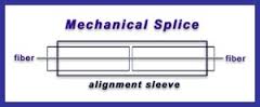
b. Fiber Optics Fusion Splicing
Picture
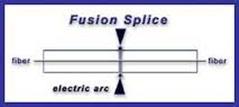
What Is Fiber Optics Mechanical Splicing?
In a mechanical splicing, two cleaved fiber tips are mechanically aligned to each other by using a precise housing alignment. An index matching gel is preinstalled between both end cleaved fiber tips to minimize back reflection and to maintain a low-loss optical interface.

It is similar function to the fusion splicing except that the fibers are held together by mechanical means rather than by permanent fusion or welding technique. 

The mechanical splice performance depends on 
a. cleaving performance
b. mechanical splice housing alignment design
c. end-user skills and patience
The Fiber Optics Mechanical Splicing  Concept 
Basically the mechanical splice process involves five steps:-
a. fiber optics stripping
b. fiber optics cleaning to remove excess of plastic buffer
c. cleaving the fiber optics ends
d. inserting the fibers into the mechanical splice housing.
This mechanical splice housing retains the fibers so their ends are in contact.
Advantages of Mechanical Fiber Optics Splices
  1. Mechanical splices require no special tools except for fiber optics stripper and cleaver.
  2. Mechanical splices can be used in situations where power supply is not readily available or the using of fusion splicing is highly impractical.
  3. Mechanical splices can be made as a temporary connections. 
  4. Mechanically aligned cleaved fibers  can be completed in few minutes thanks to precision alignment mechanism.
  5. It is a low investment especially for FTTH's drop cable installation.

Disadvantages of Mechanical Fiber Optics Splices                                  
  1. The typical insertion loss of mechanical splicing is < 0.3 - 0.5dB compared to 0.03dB using fusion splicing.
  2. Mechanical splices are typically for multimode fibers due to its larger core diameter size however single mode mechanical splices is gaining momentum in the installaton FTTH last mile.
  3. The optical performance depending on quality of cleaving, alignment mechanism and index matching gel 
  4. Above all,  the completion of good mechanical splices depending upon end-user skills and patience.
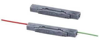
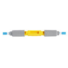
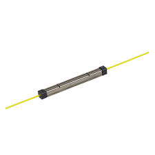
Types of Mechanical Splices
Samples of Mechanical Splices
1 Comment

    Author

    I have been in the field of fiber optics since early 1990s.  I gained fiber optics skills and knowledge via my working experience as end-user, main contractor and sub-contractor and finally as an optical fiber enterpreneur.
     

    Archives

    January 2017
    December 2016
    August 2016
    January 2016
    September 2015
    August 2015
    July 2015
    June 2015
    May 2015
    April 2015
    February 2015
    December 2014
    November 2014
    October 2014
    September 2014
    June 2014
    May 2014
    March 2014
    February 2014
    January 2014
    December 2013
    November 2013
    October 2013

    Categories

    All
    2.5mm Ferrule
    Color Blind
    Continuity
    Defective Connectors
    Defective Connectors
    Ferrule
    Fiber Breaks
    Fiber Color Code
    Fiber Optics Color Chart
    Fiber Optics Connectors
    Macrobending
    Optical Fiber Connector
    Sff
    TIA/EIA 598-A

    RSS Feed

About Us
Contact Us
Our Location
Our Fiber Optics Courses
Fiber Optics Tool Kits / Test Gears
Our Fiber Optics Blog
© 2022 Sinaran Optik
All rights reserved. 
 Be successful in fiber optics by acquiring the right Attitudes, Skills, Abilities and Knowledge
  • HOME
  • Our Services
    • Hands-ON Training >
      • 1-Hari OTDR Fiber Optik Praktikal (Melayu)
      • Ujian Kecekapan Fiber Optik
      • 1-Hari Pengujian & Pentauliahan
      • 2-Hari Fiber Optik Praktikal (Melayu)
      • 4-Hari Fiber Optik Praktikal (Melayu)
    • Sijil Kecekapan >
      • MASUK UJIAN CA
    • Accessories >
      • Patchcords
      • Pigtails
      • ProtectionSleeves
    • Test Gears & Tool Kits
    • Fiber Optics Case Studies
  • Contact Us
  • Why Us
    • Trainer's Profile
    • Our Esteemed Clients
    • Hands-ON Training Photos
    • Why Attend Our Fiber Optics Training?
  • My Blogs
    • Fiber Optics Blog
    • Biz Blog (In Malay)