|
Testing & Commissioning Optical Fiber Link -Part 1 HERE
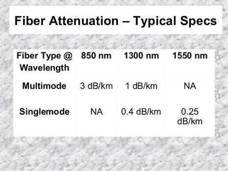
More Examples on Calculation of Optical Power BudgetAssuming our Multimode Fiber Optics cabling configuration as below : 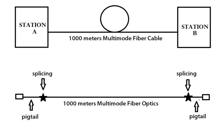 As per Singlemode, there are 2 common operating wavelength namely 850nm and 1300nm. The respective attenuation or loss as illustrated below : 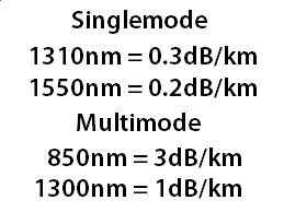 Figure 2 : Operating Wavelength Attenuation Please refer to the following link for calculation of optical fiber budget formula :- Testing & Commissioning Optical Fiber Link -Part 1 HERE Optical Power Budget Calculation Using above Figure 1 fiber optics schematic diagram followings can be deduced : a. Total length of fiber is 1km (please use OTDR to measure actual fiber length) b. 2 nos of splicings c. 2 nos of connectors d. MM operating wavelength of 850 nm - 3dB/km, 1300nm - 1dB/km Operating Wavelength at 850nm Maximum Allowable Loss = Fiber Loss + Splicing Loss + Connector Loss = (1 km x 3 dB/km) + ( 2 x 0.2dB) + ( 2 x 0.5dB) = 4.4dB Operating Wavelength at 1300nm Maximum Allowable Loss = Fiber Loss + Splicing Loss + Connector Loss = (1 km x 1 dB/km) + ( 2 x 0.2dB) + ( 2 x 0.5dB) = 2.4dB
On next articles we will emphasized on
0 Comments
Calculation of Optical Power BudgetWhat is Optical Power Budget ? The optical power budget identifies how much attenuation or loss is allowed across a fiber span while still maintaining sufficient output power for the receiver. 
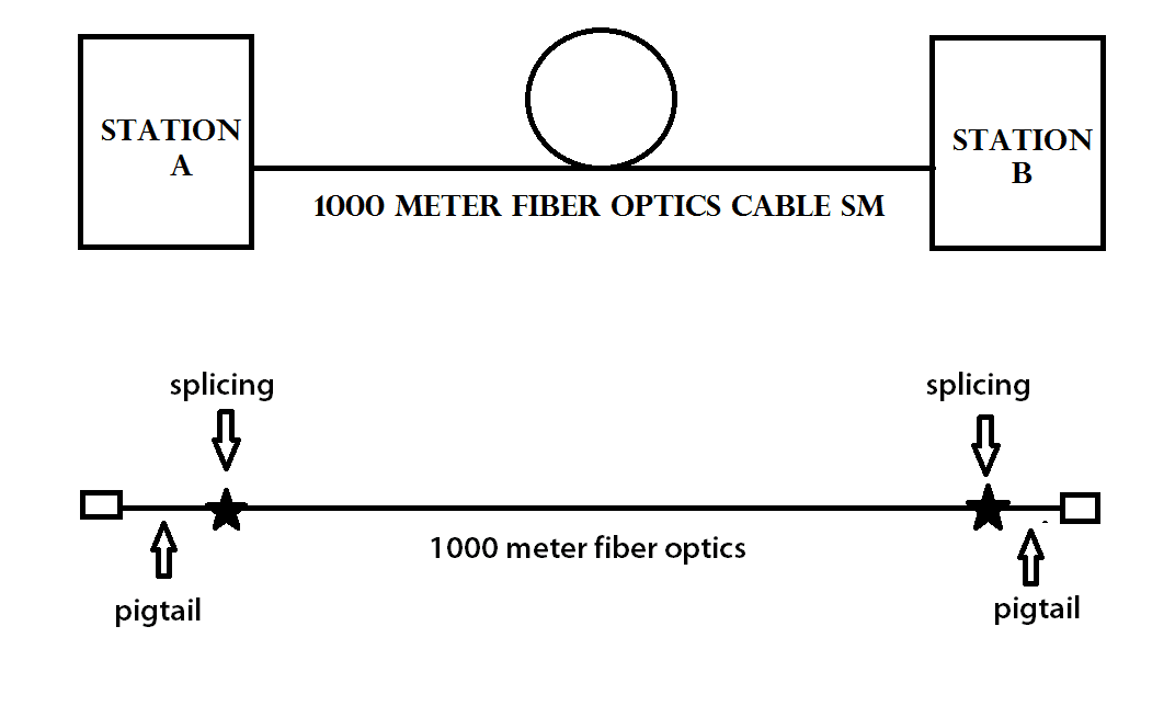 Figure 1 : Cabling Schematic Diagram
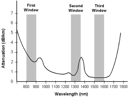
 Figure 2 : Fiber attenuation for both SM and MM How To Calculate Optical Power Budget ?
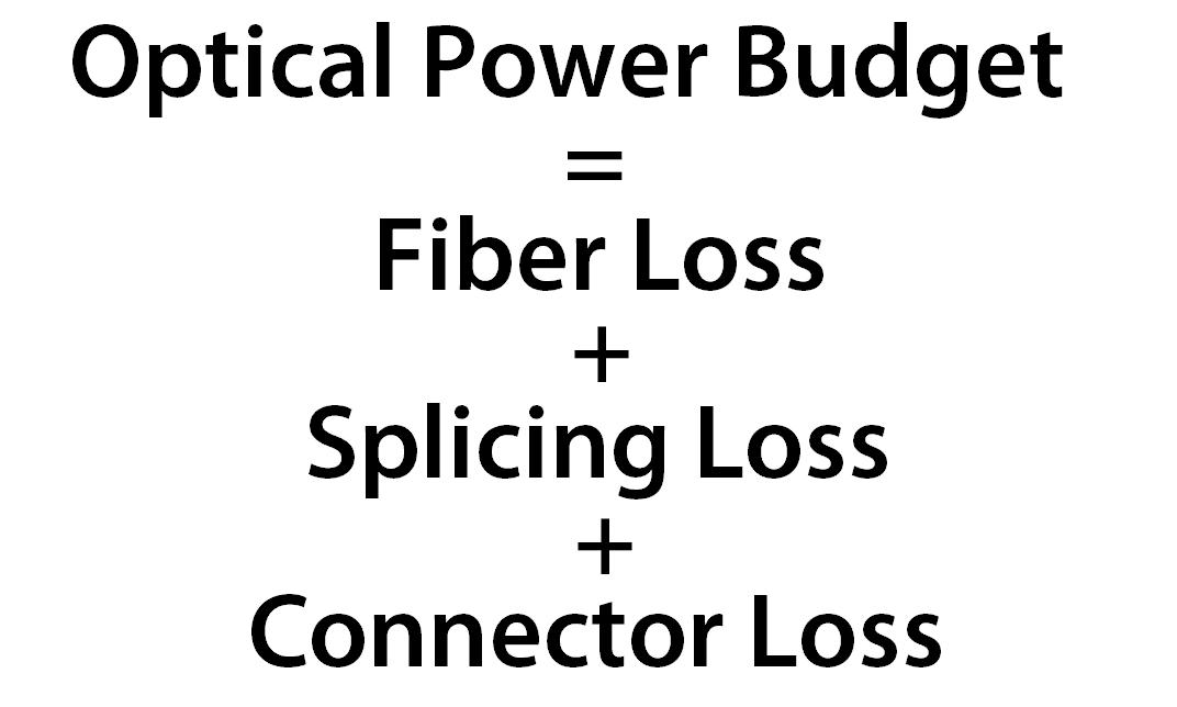 Figure 3 : Optical Power Budget Fiber Loss = Length of fiber (km) x Attenuation (dB/km) Length of fiber (km) - to get this value by using OTDR Attenuation (dB/km) - SM 1310nm - 0.3dB/km & SM 1550nm - 0.2dB/km MM 850nm - 3dB/km & MM 1300nm - 1 dB/km Splicing Loss = No. of splicing x Max splicing loss (dB) No. of splicing - total number of splicings done from Station A to Station B Max splicing loss - as per TIA/EIA recommendation 0.2dB for each splicing Connector Loss = No. of connector x Max connector loss (dB) No. of connectors - total number of connectors from Station A to Station B Max connector loss - as per TIA/EIA recommendation 0.75 dB for connectors (but we take maximum connector loss at 0.5dB) Optical Power Budget Calculation ExampleUsing above Figure 1 fiber optics schematic diagram followings can be deduced : a. Total length of fiber is 1km b. 2 nos of splicings c. 2 nos of connectors d. SM operating wavelength of 1310 nm - 0.3dB/km, 1550nm - 0.2dB/km Operating Wavelength at 1310nm Maximum Allowable Loss = Fiber Loss + Splicing Loss + Connector Loss = (1 km x 0.3 dB/km) + ( 2 x 0.2dB) + ( 2 x 0.5dB) = 1.7dB Operating Wavelength at 1550nm Maximum Allowable Loss = Fiber Loss + Splicing Loss + Connector Loss = (1 km x 0.2 dB/km) + ( 2 x 0.2dB) + ( 2 x 0.5dB) = 1.6dB
On next articles we will emphasized on
Read Optical Power Loss (Attenuation) - Part 1/5 HERE Read Optical Power Loss (Attenuation) - Part 2/5 HERE Read Optical Power Loss (Attenuation) - Part 3/5 HERE Read Optical Power Loss (Attenuation) - Part 4/5 HERE Material Losses due to manufacturing Rayleigh Scattering Fresnel ReflectionRead Optical Power Loss (Attenuation) - Part 1 HERE Read Optical Power Loss (Attenuation) - Part 2 HERE Read Optical Power Loss (Attenuation) - Part 3 HERE What is Connectors Loss? 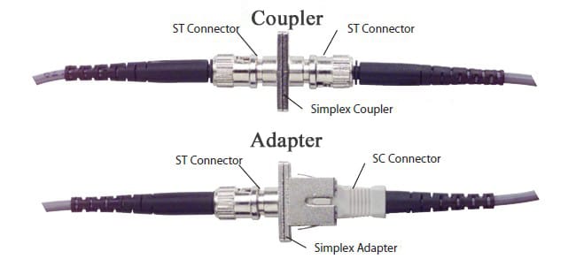 Connector loss in power budget calculation is considered as a pair of connectors being connected into an adapters as shown above diagram. As per TIA/EIA specification, the maximum loss of paired connector is 0.75dB. However, during power budget loss calculation we take maximum connector loss as 0.5dB so as to introduce loss buffer.  http://www.fiber-optic-transceiver-module.com/ Main factors that contribute to the fiber optics connector loss are :
 Other factors that may contribute to the higher losses are :
Read Optical Power Loss (Attenuation) - Part 1 HERE Read Optical Power Loss (Attenuation) - Part 2 HERE What is Splice Loss?
High splicing loss caused by few number factors. However, most high splicing loss are due to workmanship for example
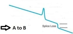
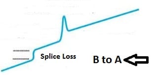
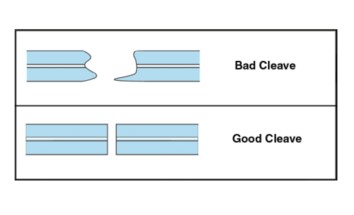 There are high splice loss due to manufacturing defects as shown below : 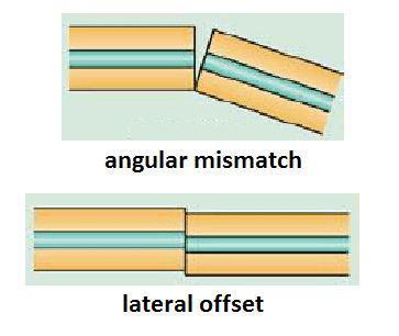 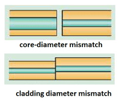 End result of splicing due to fiber misalingment or lateral offset and cladding diameter mismatched - osa.org Splicing lossSplicing loss as indicated on the fusion splicing machine is based upon estimation only. In order to get accurate splicing loss you need to check with OTDR as shown below. You need to obtain splicing loss by shooting OTDR from A to B and from B to A
Assuming the obtained both splice losses are as below : a. From A to B is -0.04dB b. From B to A is -0.02dB Using averaging formula below the final splice loss is -0.03dB 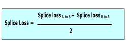 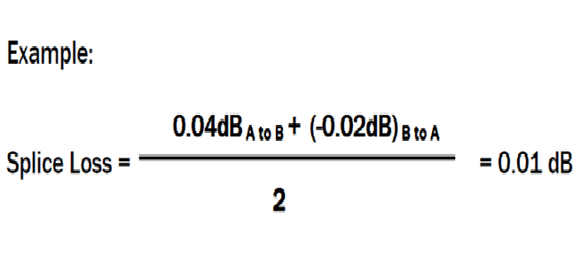 Read Optical Power Loss (Attenuation) - Part 1 HERE What is Bend Loss ?Bend loss occurs when fiber optics cable bends smaller than recommended fiber cable minimum bending radius or simply stated it is a loss induced by physical stress on fiber optics.  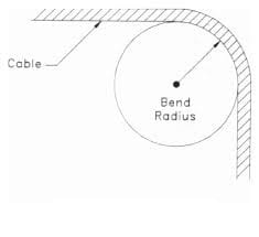
Effects of fiber optics bend on fiber optics performance ? When a fiber cable is bent smaller than minimum bending radius, the optical signal within the cable may refract and escape through the fiber cladding. 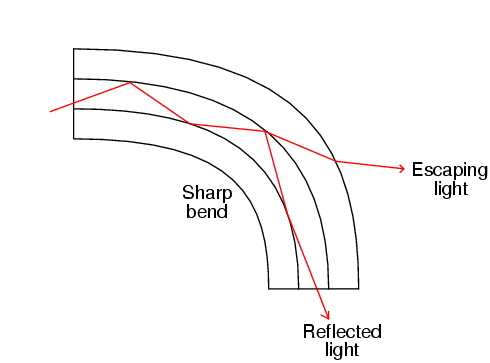 Bending can also permanentlsy damage the fiber by causing micro cracks, especially during cable installation when pulling forces are to be expected. The result is known as bend loss: a loss of signal strength that may compromise the integrity of the data transmission.; This type of fiber optics bend loss is called macrobending which can add up to to a significant to fiber optics performance. Types of Bend LossThere are two type of fiber optics bending losses. a. Macrobending loss Macrobending loss is referred to loss induced by physical stress inserted into the fiber optics itself. b. Microbending loss Microbending loss is caused by imperfection in the fiber optics internal structure might be due to manufacturing process or due to pulling method.
 Please check with fiber optic specification sheet as issued by fiber optics manufacturers
It is has become a norm in telecommunication industry whereby we will see groups of electrical engineers, copper & wireless installers are closely becoming involved with fiber optic installation, termination and testing & commissionning. Once we fully understand the simple fiber optics guidelines then the process of installation, termination & testing would be easier to handle.
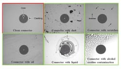
Please use following guideliines in order to secure maximum fiber optics cable performance, a. Never kink the cable. b. Never exceed recommended bend radius during or after installation. If during cable pulling the minimum radius is 20 x than the cable outer diameter and 10 x when cable at rest.  c. Do not exceed recommended tensile loads. Use external pulling grips so as the load is applied to the cable strength member and not unto the fiber itself. e. Monitor tensile loading or pulling force. f Avoid pulling long lengths in one direction. 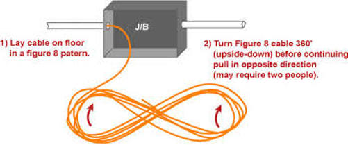 f. Do not crush put pressure on the cable. g. Plan to install extra cable protection in high-risk areas such as HDPE conduit. h. Always secure cables in all installations over ceilings or under floors. i. Survey and plan all cable routes in order to protect cable against rodents or external stress or pressure. j. Comply with all regulatory requirements and fire codes. 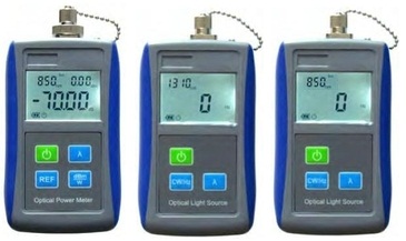 Both Light Source and Power Meter are being used to measure the actual fiber optics losses from point A to point B. The total measuread fiber optics signal lossess included following losses :- a. Fiber optics loss b. Splicing loss c. Connector loss The measured readings shall be compared with calculated maximum allowable fiber optics loss from point A to point B or link loss budget as per TIA-568 specification. Should the measured readings is above the calculated maximum loss then troubleshooting steps need to established in order to pinpoint the actual fiber optics components that are giving high losses. Generally the high losses could be attributed to one or more of the followings problems :- a. excessive fiber optics bending b. high loss splicing workmanship c. dirty connector d. dirty adapter e. improper pulling of fiber optics cable  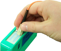 Fiber Optics Connector Cleaner is to clean end surface of connector ferrule from dirt so as to enable smooth light transmission from one connector to the other with lowest possible losses. 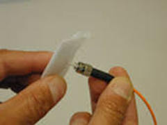 Alternatively you can use isoprophyl alcohol and normal cotton facial tissue that is available in any pharmacy stores to clean the end surface of fiber optics connector ferrule. 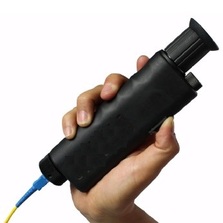 Always check end ferrule surface after cleaning either by using 100x or 400x microscope.  A good end ferrule surface (the most left photo) will provide a smooth laser transmitted from one connector to the other connector.
Otherwise you may need to repeat the cleaning process or perhaps you need to re-splice or re-terminate with new connector. |
AuthorI have been in the field of fiber optics since early 1990s. I gained fiber optics skills and knowledge via my working experience as end-user, main contractor and sub-contractor and finally as an optical fiber enterpreneur. Archives
January 2017
Categories
All
|


 RSS Feed