Here are top 5 most common fiber optics failures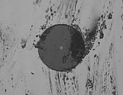 1. Dirty Fiber Optics Connectors Always clean your fiber optics connector end ferrule surface with appropriate cleaning device such isoprophyl alcohol or other recommended tools. 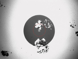 2. Poor Polishing Always check and observe your fiber optics connector end ferrule surface with fiber optics microscope.  3. Mislabelling Always check your fiber optics continuity end-to-end or connector-to-connector by using either VFL or power meter & Light source 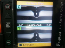 4. Bad Splicing Always double check your fusion splicing loss with an OTDR to get accurate readings. Readings appeared on splicing machine are only indication or estimation. 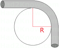 5. Excessive fiber bendings Always double check your fiber otpics management either in fiber optics termination box or fiber cable route. Try to minimise the bending as much as possible as too small bending will result in higher fiber otpics dB loss.
0 Comments
Image of a bubble at the fusion splice between two ordinary multimode fiber optics. This bubble causes extreme fiber optics splicing high loss as shown visually via Visual Fault Locator (VFL) on the right hand side image.
This bubble resulted from dirt on the fiber end surface. Proper care should be taken care of during cleaning process of fiber optics by using appropriate cleaning device such as isoprophyl alcohol. It is better to redo the splicing immediately so as to obtain minimum splicing loss possible. Fiber Optics Splicing MachinesThere are quite few numbers of splicing machine brands available in the market. The most dominated in the market are mainly from Japan i.e. Fujikura, Sumitomo and Fitel. Others available brands are Ilsintech, Inno, Yamamoto, Ericsson, Corning and at least 2 generic brands from China. Basically these available splicing machines are almost similar to one another in terms of physical appearance and the required fiber optics tool like stripper and cleaver, electrodes etc. However, the 3 steps process of splicing preparation remain the same for all brands i.e.
Perhaps in 5 -10 years time, the fiber optics stripping, cleaning and cleaving shall be done automatically by the splicing machine The cost of buying splicing machine is the most important criteria as the price is in a range between USD 3,000.00 - USD 7,000.00 per complete set. Apart from cost the other factors like after sales service plus easy to maintain fusion splicing machine are the other main issues need to be addressed carefully. Below is the latest splicing machine from Fujikura Fiber Optics carries lots and lots of data , video and voice on daily basis around the globe. One of the main reasons of using fiber optics is to have secured communications. Unlike wireless communications the issue of tapping or unauthorised eavesdropping is of the main concern. But now human managed to find a way on how to tap fiber optics by using the concept of minimum bending radius.. It look easy to tap fiber optics by locating the fiber optics cable but finding the actual fiber core to tap is another story unless you know exactly which fiber core to tap... Definition of four different International Organisationi for Standardization (ISO) multimode fibers categories. This is due to increase in demand for multimode bandwidth applications especially in Gigabit Ethernet applications. OM1 ISO 651.1 ISO/IEC 11801:2002 (OM1) Graded Inded MM - 850/1300nm - data communication OM2 ISO 651.1 ISO/IEC 11801:2002 (OM2) Graded Index MM - 850nm/1300nm - Video and data communcation OM3 ISO 651.1 ISO/IEC 11801:2002 (OM3) Graded Index MM50/125micron - Laser 850nm - Gigebit Ethernet application OM4
ISO 651.1 ISO/IEC 11801:2002 (OM4) Graded Index MM - VCSEL - 850nm - 40 GB/s , 10Gb/s data center application Is it possible to splice and joint between Singlemode and Multimode Fiber Optics? The latest fusion splicing machine is able to detect fiber of different sizes particularly between singlemode and multimode. The fusion splicing machine will display fiber type on its LED screen either as MM or SM. But will the machine proceed with the fusion splicing or jointing between fiber optics of different sizes? Let us see the video below.. a. The type of fiber optics either SM or MM is indicated clearly on the screen. b. Please observe carefully the fusion evenness between SM and MM fiber. Let us double check with Visual Fault Locator to see if there is any light leakage at splice point between MM and SM fiber optics.. Let inject laser VFL from MM side. The SM fiber optics fiber is of white color and the orange color is of MM type. There is light leakage at splice point as shown in the above video. This can be translated as high splice loss value. Let us inject laser VFL from SM side into the splice point. Would there by any light leakage at the splice point? As shown in the above video, apparently there is no light leakage detected at splice point. This is the opposite what being shown if light is injected from the MM side. What will it shown on the OTDR if fiber different sizes being spliced?
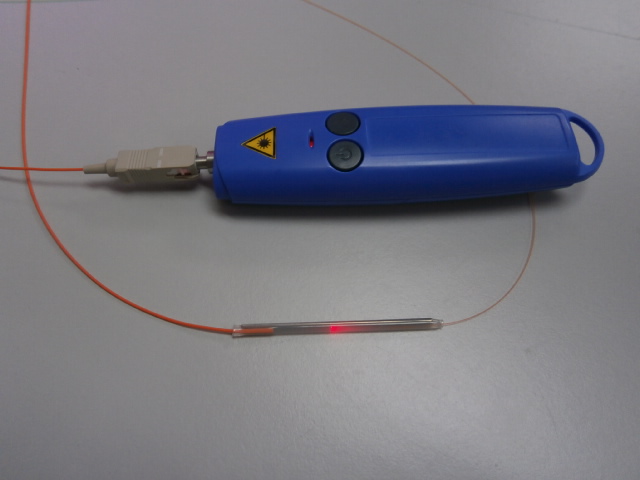
Always double check your fiber optics pigtails continuity prior to splicing.. In this case the fiber optics participants managed to find out the actual problem with regards to final insertion loss test. The fiber optics handy troubleshooting tools , VFL (Visual Fault Locator) , is used to check fiber optics pigtail continuity..
FAT FIBERReceived splicing machine message error as "FAT FIBER" as shown in the captured photo below. The fiber type was of multimode 62.5 micron. 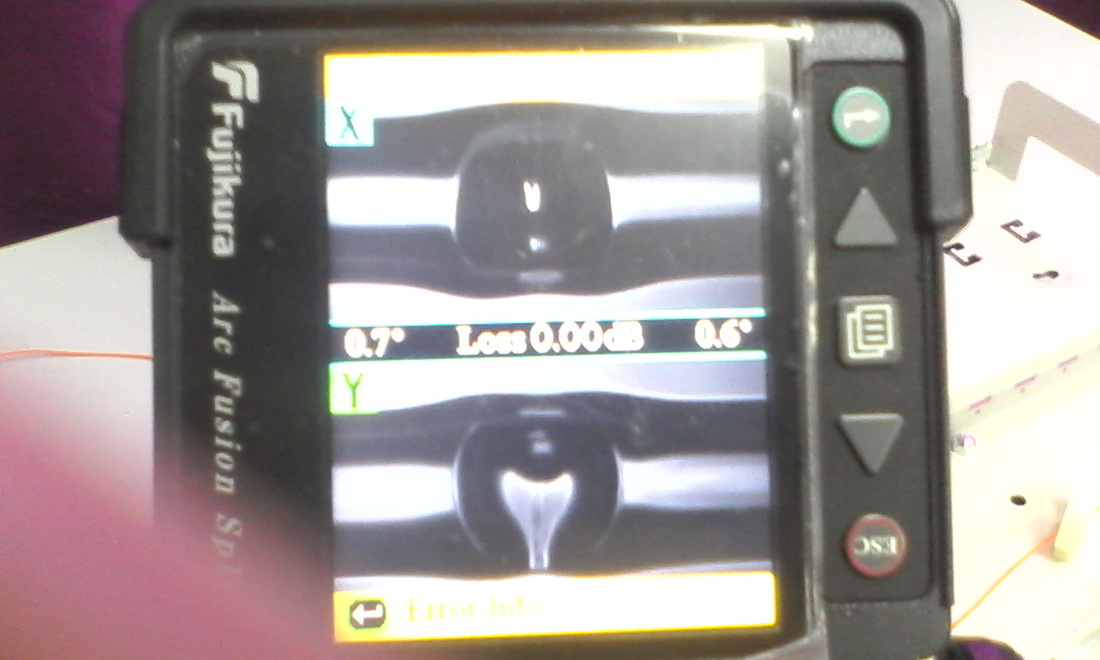
The "FAT FIBER" error message was actually a very high loss splicing loss. Using power meter & light source the final loss was measured more than 15dB for a short multimode fiber optics distance of 100 meters. A visual fiber optics fault locator was used to verify the high loss which can been seen clearly at the splicing point between fiber optics pigtails and cable. The estimation given by the splicing machine is only an indication of splicing loss. To get accurate splicing loss readings,one should use OTDR.
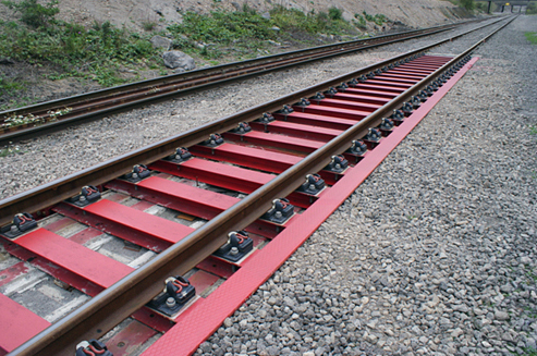
Conventional rail tracks are laid by fixing rails to sleepers laid on a ballast trackbed. Now, a team of researchers at the UK’s University of Huddersfield are developing modular, all-steel track sections that can be laid quickly and embedded with fiber optic technology, to provide instant safety alerts. They say the approach could lead to “massive cost savings and advantages in safety and efficiency”.
The Institute of Railway Research(IRR), headed by Professor Simon Iwnicki, is based at the University and is one of the partners in a €15 million, four-year project funded by the EU under its Seventh Framework Programme. Capacity4Rail aims to ensure that railways will continue to meet Europe’s transport needs, with development aims including reducing maintenance, more resilient and easily repairable points (switches), and higher-speed freight wagons. There are 47 partners, including major technology companies and European universities, and the University of Huddersfield’s IRR is working on a project entitled “modular integrated design of new concepts for infrastructure”. One of the IRR’s tasks will be to help in the development and design requirements of new track systems. Smart approach The Institute’s Head of Research, Dr Yann Bezin, commented, “We are looking at more efficient designs and methods of building a track, in a modular way rather than by laying down ballast layers and then individual sleepers and putting the rails on top. That takes a long time and requires very expensive and heavy machinery. Modular concepts allow track to be brought pre-assembled in sections for a quick installation. “A big problem is vertical support of the track,” explained Bezin. “Currently you get deterioration from one sleeper to the other or the ballast degrades and some sleepers become unsupported. A concrete sleeper is the norm, but we have studied a steel track system that uses steel beams. This gives consistency of support and better control of dynamic forces.” Bezin added that the construction of modular track sections in the factory would mean that they could be pre-equipped with smart technology. “We could make the track system intelligent. Fiber optics running along the rail would enable a network operator to know from the signal whether or not there is an unusual deformation, an indication of fatigue cracking or some other problem”. Such a condition monitoring system would simplify maintenance, adding to the efficiency gains from modular track construction. Capacity4Rail The IRR will receive more than €470,000 for its contribution to Capacity4Rail. In addition to work on modular track sections, the Institute’s researchers, who are based in specially equipped labs at the University of Huddersfield, will study new designs for the construction of switches and crossings. The IRR will be investigating resilient new materials for crossings and switches, working with the metallurgist Jay Jaiswal, formerly of Tata Steel, who has been appointed a visiting professor at the University of Huddersfield. The Institute will also be working with major companies such as Systra, which has constructed all of France’s and half of the world’s high-speed lines. The Capacity4Rail research will build on the findings of previous projects that the IRR has been closely involved with, such as the EU-backed Innotrack, which has investigated many of the technical challenges posed by the EC’s goal of doubling rail passenger traffic and tripling freight traffic by 2020. About the Author Matthew Peach is a contributing editor to optics.org. 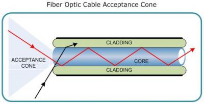 Only light that enters the fiber core within a certain range of angles or other known as critical angle or acceptance cone, can be successfully travelling through the length of the fiber. 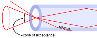 The light that does enter the fiber core but not within the acceptance cone will normally escape or lost into fiber optics cladding. 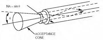 The size of acceptance cone is a function of the refractive index difference between the fiber optics core and cladding.  where n(core) is core refractive index and n(cladding) is cladding refractive index.
However, all these factors are being taken care with due diligence during the designing and manufacturing process of fiber optics preform. |
AuthorI have been in the field of fiber optics since early 1990s. I gained fiber optics skills and knowledge via my working experience as end-user, main contractor and sub-contractor and finally as an optical fiber enterpreneur. Archives
January 2017
Categories
All
|

 RSS Feed