SINARAN OPTIK
  • HOME
  • Our Services
    • Hands-ON Training >
      • 1-Hari OTDR Fiber Optik Praktikal (Melayu)
      • Ujian Kecekapan Fiber Optik
      • 1-Hari Pengujian & Pentauliahan
      • 2-Hari Fiber Optik Praktikal (Melayu)
      • 4-Hari Fiber Optik Praktikal (Melayu)
    • Sijil Kecekapan
    • Accessories >
      • Patchcords
      • Pigtails
      • ProtectionSleeves
    • Test Gears & Tool Kits
    • Fiber Optics Case Studies
  • Contact Us
  • Why Us
    • Trainer's Profile
    • Our Esteemed Clients
    • Hands-ON Training Photos
    • Why Attend Our Fiber Optics Training?
  • My Blogs
    • Fiber Optics Blog
    • Biz Blog (In Malay)

OTDR Setup -  Index of Refraction & Fiber Distance 

6/2/2015

5 Comments

 
Picture
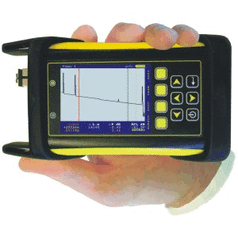
All OTDRs regardless of brand have four basic setup requirement i.e. the OTDR user is required to key in these four basic data parameters into OTDR in order to get good and accurate fiber trace analysis.

The required data parameters are :-
  1. Testing Range - Refer to Article HERE
  2. Pulse Width - Refer to Article HERE
  3. Index of Refraction 
  4. Averaging Time
Index of Refraction
Picture
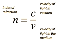
The relationship between distance and velocity or speed is as shown below -
You can review previous article on Index of Refraction HERE or HERE

As previously mentioned index of refraction measures the speed of light in optical medium. It is a function of velocity of light in vacuum and velocity of light in the opticel fiber medium or simply stated as below -

Picture
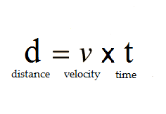
Velocity of light in fiber optics can be further expressed in terms of velocity of light in vacuum and index of refraction. This is done by rearranging the index of refraction equation as stated above.
Picture
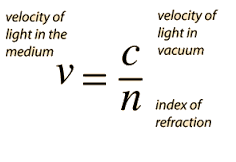
Knowing that C or velocity of light in vacuum is a constant value
Picture
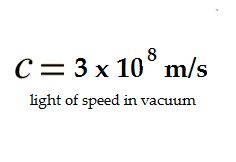
Then the distance of fiber optics as measured by OTDR can be simplied as shown below
Picture
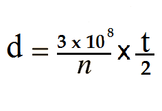
The index of refraction, n,  is a known value which can be obtained from the fiber optics manufacturer. While t , OTDR pulse width  and its backscatter light travelling time , can be measured by OTDR automatically ie. the initial time laser pulse width launched into fiber optics and time taken by backscattered light returned back into OTDR.

Therefore, the measured of fiber optics distance is a function of index of refraction.
As value of IOR increases the measured fiber optic distance or length is getting shorter.
Picture
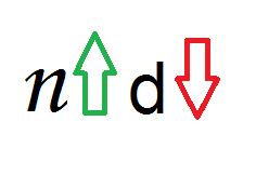
As value of IOR decreases the measured fiber optic distance or length is getting longer.
Picture
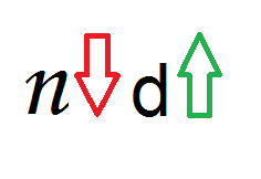
If the OTDR index of refraction does not match to that of fiber optics under testing IOR then the OTDR distance traces might show the incorrect results. 

If the fiber optics under testing IOR is not known, then the end-user can use the OTDR default  IOR setting.

Typical fiber optics IOR value is between 1.4000 to 1.6000

Picture
Rule of Thumb
Always obtain the fiber optics Index of Refraction values from corresponding fiber optics manufacturer.
5 Comments
Mark Banner
9/25/2019 04:37:08 pm

It is too much important blog on fiber optic. From your blog, we get much valuable information on this topic. Thanks for sharing this informative blog with us.

Reply
anton
8/30/2020 01:37:23 pm

I Think same as your openion. Too much importand this information

Reply
Trent Riley link
11/26/2020 07:14:11 pm

Thanks for thiss blog post

Reply
Voip Service Providers NZ link
2/23/2021 03:47:02 pm

These are some great information that you have shared here about otdr setup index of refraction fiber distance . I really loved it and thank you very much for sharing this with us. You have a great visualization and you have really presented this content in a really good manner.

Reply
Arizona Tile Installation link
11/30/2022 10:33:22 pm

Appreciaate you blogging this

Reply


Leave a Reply.

    Author

    I have been in the field of fiber optics since early 1990s.  I gained fiber optics skills and knowledge via my working experience as end-user, main contractor and sub-contractor and finally as an optical fiber enterpreneur.
     

    Archives

    January 2017
    December 2016
    August 2016
    January 2016
    September 2015
    August 2015
    July 2015
    June 2015
    May 2015
    April 2015
    February 2015
    December 2014
    November 2014
    October 2014
    September 2014
    June 2014
    May 2014
    March 2014
    February 2014
    January 2014
    December 2013
    November 2013
    October 2013

    Categories

    All
    2.5mm Ferrule
    Color Blind
    Continuity
    Defective Connectors
    Defective Connectors
    Ferrule
    Fiber Breaks
    Fiber Color Code
    Fiber Optics Color Chart
    Fiber Optics Connectors
    Macrobending
    Optical Fiber Connector
    Sff
    TIA/EIA 598-A

    RSS Feed

About Us
Contact Us
Our Location
Our Fiber Optics Courses
Fiber Optics Tool Kits / Test Gears
Our Fiber Optics Blog
© 2022 Sinaran Optik
All rights reserved. 
 Be successful in fiber optics by acquiring the right Attitudes, Skills, Abilities and Knowledge
  • HOME
  • Our Services
    • Hands-ON Training >
      • 1-Hari OTDR Fiber Optik Praktikal (Melayu)
      • Ujian Kecekapan Fiber Optik
      • 1-Hari Pengujian & Pentauliahan
      • 2-Hari Fiber Optik Praktikal (Melayu)
      • 4-Hari Fiber Optik Praktikal (Melayu)
    • Sijil Kecekapan
    • Accessories >
      • Patchcords
      • Pigtails
      • ProtectionSleeves
    • Test Gears & Tool Kits
    • Fiber Optics Case Studies
  • Contact Us
  • Why Us
    • Trainer's Profile
    • Our Esteemed Clients
    • Hands-ON Training Photos
    • Why Attend Our Fiber Optics Training?
  • My Blogs
    • Fiber Optics Blog
    • Biz Blog (In Malay)