|
IP stands for International Protection or Ingress Protection marking as defined by International Standard IEC 60529 classifies and rates the degree of protection provided against intrusion (body parts such as hands and fingers), dust, accidental contact, and water by mechanical casings and electrical enclosures. It is published by the International Electrotechnical Commission (IEC). The equivalent European standard is EN 60529. 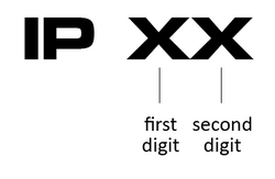 for example IP67 signifies the enclosure is protected against dust and water as per IP rating code indicated below. 
0 Comments
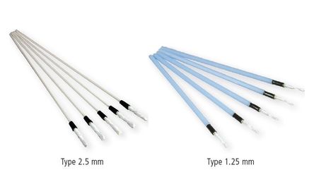
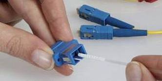
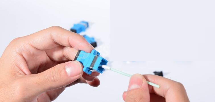
The fiber optics connectors or adapters has been identified one of the major causes of fiber optics system failure or error. This is due to dust blocking the laser light or dust accumulated in the adapters.
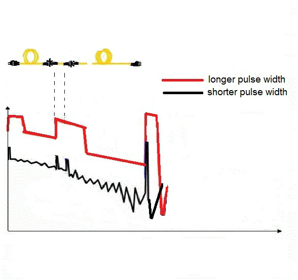
The fiber optics connectors need to be thoroughly cleaned using alcohol isoprophyl before being connected into the system or using any other proper cleaning tool and fiber optics adapters are also occassionally need to be thoroughly cleaned using adapter cleaner sticks. Have been quite sometime this blog has not been updated. Please come back soon next week with more fiber optics news.  Almost perfect fiber optics single mode mechanical splicing 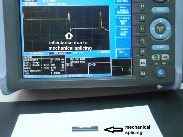 Larger photo of mechanical splicing 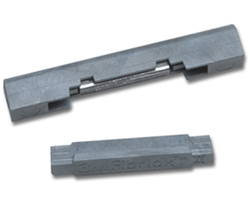 OTDR with different settings of Pulse Width
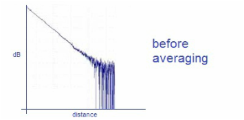
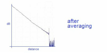
At Pulse Width 3ns 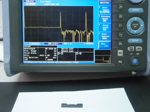 At Pulse Width 20ns 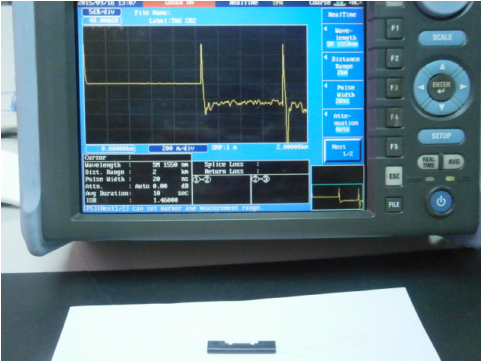 At Pulse Width of 100ns 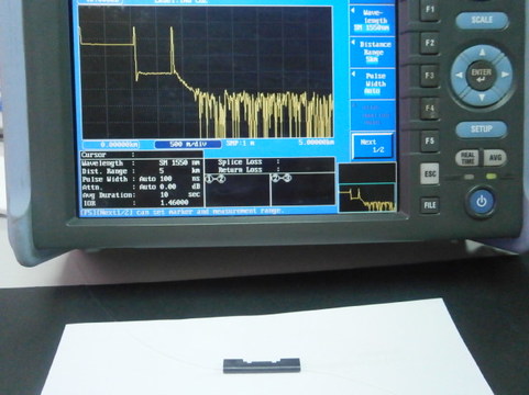 At Pulse Width 1micronsecond 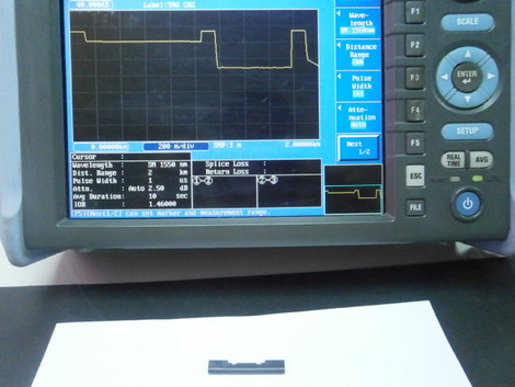 In the change from glass to air, energy reflected back to the OTDR is of such intensity that the light pulse is reflected off of the connector at the OTDR and is again returned a second time. As the OTDR converts the travel time of the light pulse into distance, the reflective event is painted on the screen a second time—thus, a ghost. - Charles Lohrman 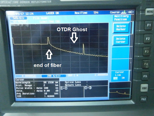 Fiber Optics Network 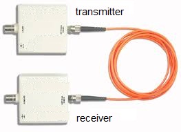 Transmitter A network device that convert incoming electrical signal into optical signal for transmisson down an optical fiber link. 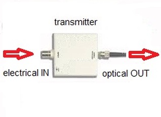 Data, voice and video are digitized and converted into electrical signals which pass through Fiber Optics Transmitter and converts electrical signals into an optical signal output. Receiver A network device that converts an incoming optical singal into an electrical signal for transmission down an electrical link. 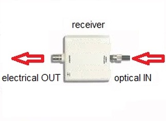 Optical signal which pass through Fiber Optics Receiver converts optical signals into an electrical signal output. Transceiver Transceiver is a combination of both fiber optics transmitter and receivers into one component. It is commonly called Small Form Factor Pluggable Transceiver or SFP. 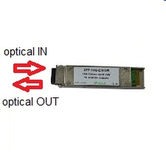  All OTDRs regardless of brand have four basic setup requirement i.e. the OTDR user is required to key in these four basic data parameters into OTDR in order to get good and accurate fiber trace analysis. The required data parameters are :- What is Averaging ? Averaging refers to time taken to have a good OTDR traces as shown below.
However, the longer averaging time would provide better OTDR traces but it wil be time consuming for OTDR to provide such traces. The before averaging or low averaging is sufficient should the end-user only interested to find out the approximate fiber optics link distance. 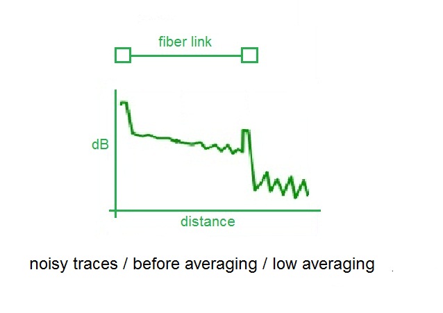 The about right averaging is able to provide good measurement loss. 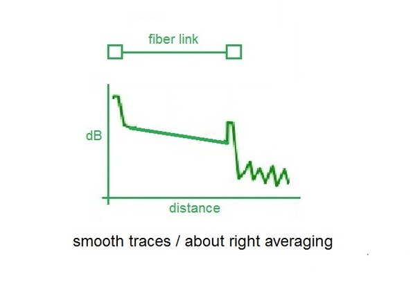 The higher averaging time provides better OTDR traces but OTDR takes extra times to do the averaging and display better traces. 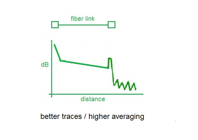
 All OTDRs regardless of brand have four basic setup requirement i.e. the OTDR user is required to key in these four basic data parameters into OTDR in order to get good and accurate fiber trace analysis. The required data parameters are :- What is Pulse Width? 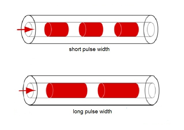
|
AuthorI have been in the field of fiber optics since early 1990s. I gained fiber optics skills and knowledge via my working experience as end-user, main contractor and sub-contractor and finally as an optical fiber enterpreneur. Archives
January 2017
Categories
All
|

 RSS Feed