 All OTDRs regardless of brand have four basic setup requirement i.e. the OTDR user is required to key in these four basic data parameters into OTDR in order to get good and accurate fiber trace analysis. The required data parameters are :- Fiber Optics Testing Range or Distance of Fiber Optics to Test Many OTDRs have automatic length detection functions unless the end-user knows the approximate fiber distance then testing range can be set manually. The following diagrams provide OTDR traces in accordance to OTDR testing range settings. Too Short Testing Range 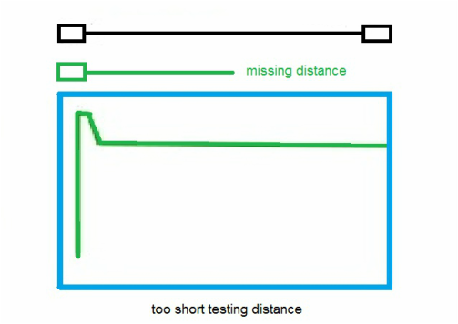
Too Long Distance Range 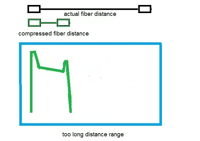
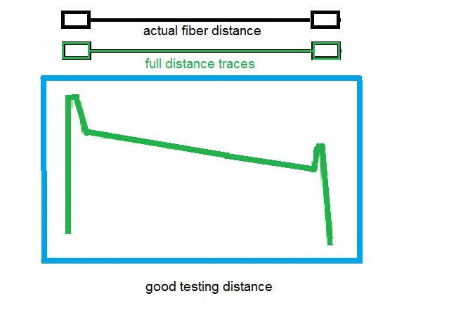
Good Distance Range
2 Comments
The Iron Ring is a ring worn by many Canadian-trained engineers, as a symbol and reminder of the obligations and ethics associated with their profession. From a concept originated in 1922, the ring is presented to graduates in a closed ceremony known as The Ritual of the Calling of an Engineer, developed with the assistance of English poet Rudyard Kipling.  The ring symbolizes the pride which engineers have in their profession, while simultaneously reminding them of their humility. The ring serves as a reminder to the engineer and others of the engineer’s obligation to live by a high standard of professional conduct. It is not a symbol of qualification as an engineer – this is determined by the provincial and territorial licensing bodies. 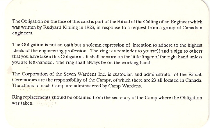   All OTDRs regardless of brand have four basic setup requirement i.e. the OTDR user is required to key in these four basic data parameters into OTDR in order to get good and accurate fiber trace analysis. The required data parameters are :- Index of Refraction 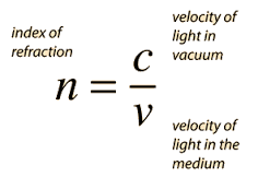 The relationship between distance and velocity or speed is as shown below - You can review previous article on Index of Refraction HERE or HERE As previously mentioned index of refraction measures the speed of light in optical medium. It is a function of velocity of light in vacuum and velocity of light in the opticel fiber medium or simply stated as below - 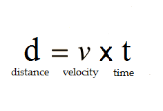 Velocity of light in fiber optics can be further expressed in terms of velocity of light in vacuum and index of refraction. This is done by rearranging the index of refraction equation as stated above. 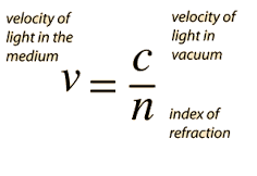 Knowing that C or velocity of light in vacuum is a constant value 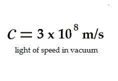 Then the distance of fiber optics as measured by OTDR can be simplied as shown below 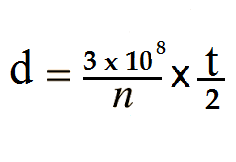 The index of refraction, n, is a known value which can be obtained from the fiber optics manufacturer. While t , OTDR pulse width and its backscatter light travelling time , can be measured by OTDR automatically ie. the initial time laser pulse width launched into fiber optics and time taken by backscattered light returned back into OTDR. Therefore, the measured of fiber optics distance is a function of index of refraction. As value of IOR increases the measured fiber optic distance or length is getting shorter.  As value of IOR decreases the measured fiber optic distance or length is getting longer. 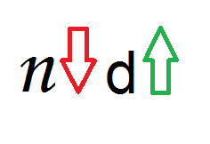 If the OTDR index of refraction does not match to that of fiber optics under testing IOR then the OTDR distance traces might show the incorrect results. If the fiber optics under testing IOR is not known, then the end-user can use the OTDR default IOR setting. Typical fiber optics IOR value is between 1.4000 to 1.6000
What is fiber optics splicing ? Fiber Optics splicing is the process of jointing or holding two fibers together There are two methods of fiber optics splicing namely :- a. Fiber Optics Mechanical Splicing 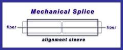 b. Fiber Optics Fusion Splicing 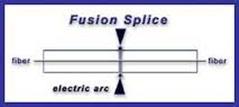 What Is Fiber Optics Mechanical Splicing? In a mechanical splicing, two cleaved fiber tips are mechanically aligned to each other by using a precise housing alignment. An index matching gel is preinstalled between both end cleaved fiber tips to minimize back reflection and to maintain a low-loss optical interface. It is similar function to the fusion splicing except that the fibers are held together by mechanical means rather than by permanent fusion or welding technique. The mechanical splice performance depends on a. cleaving performance b. mechanical splice housing alignment design c. end-user skills and patience The Fiber Optics Mechanical Splicing Concept Basically the mechanical splice process involves five steps:- a. fiber optics stripping b. fiber optics cleaning to remove excess of plastic buffer c. cleaving the fiber optics ends d. inserting the fibers into the mechanical splice housing. This mechanical splice housing retains the fibers so their ends are in contact. Advantages of Mechanical Fiber Optics Splices
Disadvantages of Mechanical Fiber Optics Splices
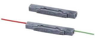
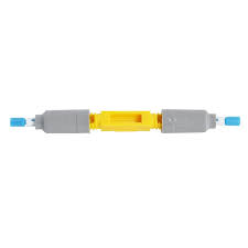
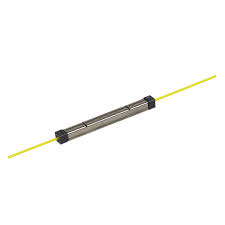
Types of Mechanical Splices Samples of Mechanical Splices
The basic optical property of a material is the index of refraction. It is also one of the key parameter that needs to be key-in into OTDR as to get accurate result on actual fiber optics distance measurement. The index of refraction (n) measures the speed of light in an optical medium.  The speed of light (c) in free space or vacumm is 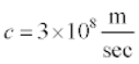 Therefore index of refraction of a material is equivalent to :-  When light enters a different material ( from glass into air or from air into glass)is the speed changes. This causes the light to bend or refract. Light will always travel slower in the fiber material than in air. 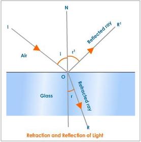 The index of refraction for glass is approximately 1.50 or lower.
The index of refraction for air is exactly 1.00. In order to get the actual fiber optics length measurement using OTDR, one is required to enter fiber optics index of refraction into one of OTDR key parameters. The fiber optics index of refraction could be obtained from the fiber optics cable manufacturer. Insertion loss and return loss are an indication of important values to evaluate the quality of fiber optic patch cords, pigtails or connectors termination. What is Insertion Loss ? 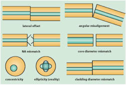 In telecommunications, insertion loss is the loss of signal power resulting from the insertion of a device in a transmission line or in other words Insertion loss refers to the fiber optic light loss caused when a fiber optic component insert into one another to form the fiber optic link. Absorption, misalignment or air gap between the fiber optic components are the main cause contribution to Insertion Loss. What is Return Loss ? 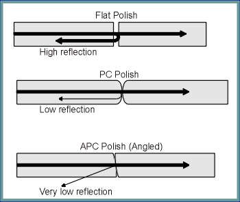 In telecommunications, return loss is the loss of power in the signal reflected by a discontinuity in fiber optics (connectors) or in other words Return loss is the fiber optic light gets reflected back at the connection point. 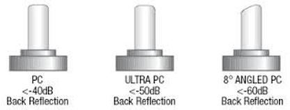 What Does High Return Loss Indicate?
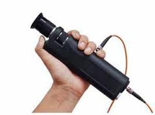
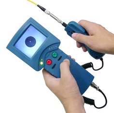
First you will need to perform a visual inspection of the connector ferrule endface by using either a handheld optical microscope or a fiber optic video probe.
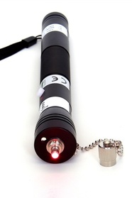
This visual inspection will determine the type of action required to repair the faulty connector. If the connector only has minor damage, (i.e., scratches, small chips, or small pits), then re-polishing the connector will usually fix the problem. 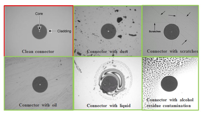 If the visual inspection determines that the connector is shattered or there is no continuity, then a new fiber optic connector must be replaced or terminated. 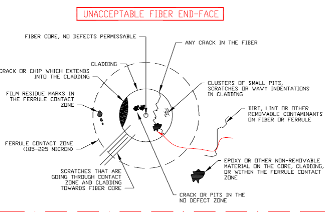 First you have to locate the damaged location of the fiber optics cable. This can be done either by using a Visual Fault Locator (VFL) or an Optical Time Domain Reflectometer (OTDR).
Based on the location of the fiber cable damage as indicated either or both VFL and OTDR you can decide on a what type of repair required.
The repair might required a fusion splicing between cables, a pigtail assembly, replacement of faulty adapters, macrobending in splicing tray or faulty patchcord due to rodents. 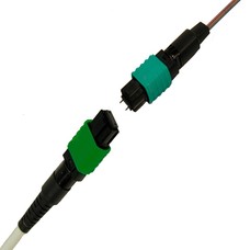 Sumitomo’s Lynx2-MPO is the industry’s first MPO fusion splice-on field installable connector for customized, on-site, terminations. The breakthrough technology of the Lynx2-MPO meets the needs of the network for greater optical fiber density and addresses the connectivity demands for faster and easier terminations, upgrades, repairs and restorations, and significant cost savings required for today’s data center, enterprise network, outside plant, OEM, central office, and virtually any FTTx network application. MTP® compatible, the Lynx2-MPO is the perfect solution for optical fiber ribbon and loose tube round cord and patch cord terminations. Like all Lynx2 fusion splice-on connectors (SC, LC, FC, and ST), the Lynx2-MPO allows the technician to make permanent terminations with the exact cable length for fast and easy installations and upgrades at the work site. The on-site customization facilitated by the Lynx2 connectivity method eliminates the risk of shorts and slack, repair lag, and logistic delays associated with preterminated cables and pigtails — making the Lynx2-MPO your best choice in customized fiber termination. |
AuthorI have been in the field of fiber optics since early 1990s. I gained fiber optics skills and knowledge via my working experience as end-user, main contractor and sub-contractor and finally as an optical fiber enterpreneur. Archives
January 2017
Categories
All
|


 RSS Feed